Documents
An important aspect of any project like ours is documentation.
Listed here are all the design papers written for this project,
from early design to finished product, to show how we developed
our initial ideas into a real, functioning system.
Proposal
The project proposal pitches and describes our initial idea and the problem we wanted to solve. It also gives a few ideas we had on how we might solve it. Also included is the power point we created to sell the idea of our project.
Associated Documents: Project Proposal, Project Proposal Presentation

High Level Design
This document was written in the early stages of our project and lays out the high level design of our project. It describes our inital goals, breaks the projct down into subsytems, details our basic system requirments, lists open quesitions to be answers, and estimates our budget.
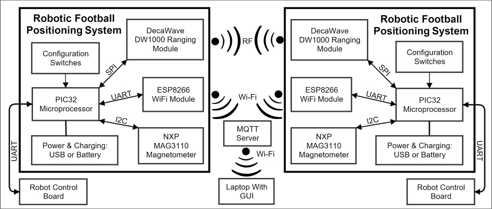
To create it we drew the image on the left in early December. As you can see, this image is similar to our completed block diagram (shown below).
Associated Documents: High Level Design
Low Level Design
This document was written at about the halfway point through our project and discribes our low level design of the positioning system. It details the overall system and subsystem reqirements and provides a discription of the overall operation.
Associated Documents: First Review of the Low Level Design
Progress
These documents were created as part of making the project work. They include all the tasks that were assigned and completed during the process, the DWM1000 Module datasheet, PIC32MX5XX/6XX/7XX datasheet, the MAG3110 datasheet, and distance measurements used for antenna calibration. Unfortunately the ESP8266-1 datasheet is not publicly available.
Associated Documents: Assigned Tasks, DWM1000 Datasheet, PIC32MX795F512H Datasheet,MAG3110 Datasheet, Calibration Distance Measurements
Final Report
The final report details the work that went into the project. This includes explanation of subsystems, testing results, implementation for the demonstration, and future improvements. The appendices, containing the code, are separate documents from the report itself due to space. Complete board schematics are available here. The poster used during our final demonstration is also given as it summarizes the information from the final report.
Associated Documents: Final Report, Appendix A, Appendix B, Appendix C, Final Demonstration Poster
Code
All the code used for our project is found in the appendices of the final report. However, we have listed the main function for our board (Appendix A) to provide an understanding of its basic functionality.
/*
 * @file main.c
 * @author Katherine Sanders
 *         Eddie Hunckler
 *         Stephen McAndrew
 * @brief Program to run RFPS system
 *
 * edited 26.4.17
 */

#include "deca_device_api.h"
#include "deca_regs.h"
#include "functions17.h"
#include "lcd.h"
#include "magnetometer.h"
#include "port.h"
#include "SDlib16.h"
#include "sleep.h"
#include <xc.h>
#include <stdio.h>
#include <stdlib.h>
#include <string.h>

typedef unsigned long long uint64;
uint8 switch1;
uint8 switch2;
uint8 switch3;
int enableWifi;
uint8 num;

void main(void)
{
	serial_init(115200);
	serial_3_init(115200);
	MAG3100_init();

	/* Get the data from the configuration switches */
	configDIP();
	enableWifi = DIP8;
	switch3 = DIP3;
	switch2 = DIP2;
	switch1 = DIP1;

	/* Use switch positions to determine module type - output to UART1 and UART3 */
	determine_parameters(switch1, switch2, switch3);
	MEASUREMENT_PIN = 1;

	if(switch1 ==0)
	{
		initializer(enableWifi); //output to UART1, UART3
	}
	else
	{
		responder(num, enableWifi); // output to UART3
	}
}